Options: Modeling Aids
Grid Snap on
Turns on grid snap.
Turns on ortho and sets the ortho angle.
Planar mode on
Turns on planar mode.
Disable object snaps
Temporarily suspends set object snaps.
Project object snaps to CPlane
Projects object snaps to the construction plane in the active viewport.
Snap to locked objects
Snaps work on locked objects and on objects on locked layers.
Use apparent intersections
The Intersection object snap does not need to find objects that intersect in 3-D space. The objects only need to appear to intersect in the active viewport.
Sets the object snap activation area radius in pixels. When the cursor is within this distance to the point to snap to, the marker jumps to the point to snap to.
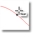
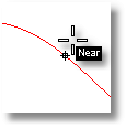
Dynamic object snap display
Controls the appearance of the object snap label.
Note: Turning on cursor tooltips turns off object snap labels automatically.
Black on white
Displays black lettering in a white box.
White on black
Displays white lettering in a black box.
None
Turns off dynamic object snap display.
Specifies the behavior of construction planes in the viewports.
The construction plane of each viewport is independent from all of the other constructions planes.
The behavior of the construction planes in the viewports is linked. They all share the same origin and are positioned normal to each other. Moving, rotating, or otherwise changing the construction plane in one viewport, changes the construction planes in the other viewports, so the 90-degree/right angle/normal orientation of the construction planes is maintained.
If a construction plane is defined in some view, the Front view for example, and Universal mode is enabled, then the construction plane that was defined will be the Front plane of the new universal plane.
|
Standard > Options Tools > Options Properties > Options (Right click) Standard > Options (Right click)
Tools > Options |
Enables object dragging parallel to the construction plane, view, world x-y axis, or surface.
Steps:
Click an option.
Options
CPlane
Sets object dragging parallel to the construction plane.
World
Sets object dragging parallel to the world x-y plane.
View
Sets object dragging parallel to the view plane.
UVN
Sets surface control point dragging to conform to the surface u-, v-, and normal directions.
Next
Sets object dragging to the next mode in the list.
|
Point Editing > Change Drag Mode
Edit > Change Drag Mode |
Toggles grid snap mode.
When Snap is on, the marker "snaps" between grid snap points, whose distance apart is set by the SnapSize command or by the Document Properties dialog box, Grid page.
Grid snap is overridden by object snaps and coordinate input, and partially overridden by angle and distance constraint.
|
None
None |
Sets the grid snap spacing in Rhino units.
Steps:
Type the snap spacing value.
|
Object Snap > Snap Size (Right click)
None |
Turns grid snap on, off, or toggles the current state.
Steps:
Click an option.
Options
On
Off
Toggle
|
None
None |
Limits successive picked locations to the same construction plane elevation as the previous location.
Steps:
Planar mode aids in creating planar objects with commands that allow free picking. Successive points have the same construction plane elevation.
Example
From the Curve menu, click Free-form, then click Control Points.
Pick the first point in the lower part of the Top viewport.
Move the cursor to the Front viewport and continue drawing.
You will see that all the points you pick define a planar curve at the same elevation in the Front viewport. (Watch the Top and Right viewports). That elevation for the Front viewport was defined by the very first point you placed in the Top viewport. With Planar off, the subsequent points would be at elevation 0 in the Front viewport.
Notes
Each point picked in a viewport will have the same elevation from that viewport's construction plane as the previous point, regardless of where the previous point was picked.
Planar mode can be overridden with elevator mode or object snaps.
|
None
None |
Turns Planar mode on, off, or toggles the current state.
Steps:
Click an option.
This is useful for inclusion in a script file for the ReadCommandFile command.
Options
On
Off
Toggle
|
None
None |
Restricts the movement of the cursor to multiples of a specified angle from the last point created.
Notes
The Ortho command, clicking Ortho in the status bar, and the F8 key, are all toggles. Holding the Shift key changes the mode while you hold the key down.
The SetOrtho command prompts for a setting with the options On, Off, and Toggle. This is useful for inclusion in a script for the ReadCommandFile command.
When Ortho is on, marker movement is restricted to points at multiples of a specified angle from the last point created. The default angle is 90 degrees.
|
Object Snap > Ortho Toggle
None |
Sets the angle at which the movement of the cursor is restricted when ortho mode is active.
Steps:
Type the new angle.
Note: You can also set the ortho angle from the Options dialog box, Modeling Aids page.
|
Object Snap > Set Ortho Angle (Right click)
None |
Turns ortho mode on, off, or toggles the current state.
Steps:
Click an option.
Note: This is useful for inclusion in a script file for the ReadCommandFile command.
Options
On
Off
Toggle
|
None
None |