Options: Appearance Advanced Display Settings
Manages the Advanced Settings modes.
Actions
New
Create a new custom display mode.
Copy
Copy a display mode.
Delete
Delete a custom display mode.
Import
Import a display mode.
Export
Export a display mode.
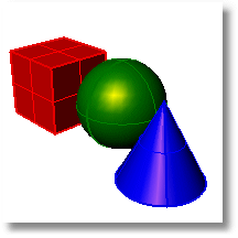
Specifies display settings.
Name of display mode.
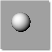
Specifies the viewport background color.
Use settings specified in Options > Appearance > Colors.
Specify the color.
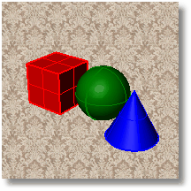
Specifies an image for the viewport background.
Image file name
Type or browse for the file name.
Top Color/Bottom Color
Specify the color.
Top Left Color/Top Right Color/Bottom Left Color/Bottom Right Color
Specify the color.
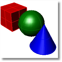
Object's color
Use the color specified in the object's Properties.
Gloss
Transparency
Single color for all objects
Gloss
Transparency
Single object color
Specify the color.
Rendering material
Shade using rendering material.
Custom material for all objects
Click the Customize button to specify the custom material.
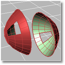
Use front face settings
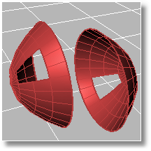
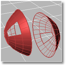
Cull backfaces
Display backfaces invisible.
Use object's color
Use the color specified in the object's Properties.
Gloss
Transparency
Single Color for all backfaces
Gloss
Transparency
Single backface color
Specify the color.
Rendering material
Custom material for all backfaces
Click the Customize button to specify the custom material.
|
|
|

Edge Thickness (pixels)
Color reduction %
Use lights on layers that are off
Draw lights using light color
Lighting method
Used when no other lights are specified or are used.
Uses the light objects that exist in the current model/scene.
Sets up to eight custom lights.
Customize
Set an x-, y-, and z-direction and color for each light.
Options
Light #
Direction
Setting the directional value to 0,0,0 means "Don't use this light", since that has no direction.
Color
Specular
Use current scene lights
Identifies any lights in the scene that are Directional lights, and uses up to eight lights to populate the fields in the dialog.
Notes:
This option deletes all current values in the dialog, even if there were no directional lights found in the scene.
The directional lights are converted to camera-directional lights using world-coordinates.
Apply Now
Applies the lighting to the model
Click the color bar to specify the color in the Select Color dialog box.
Specifies the grid settings for the display mode.
Grid Settings
Grid usage
Use document settings
Use settings specified in Document Properties > Grid.
Use mode-specific settings
Specify the settings in individual modes.
Show grid
Show grid axes
Show world axis icon
World axis icon color usage
Application settings
Use default setting.
Same as grid axis colors
Set colors for grid axes in Options> Appearance > Colors.
Use specified custom colors
Click the color bars to specify the colors in the Select Color dialog box.
Display construction plane z-axis.
Set size of axes as a percentage of the grid extents.
Grid appearance
Note: Transparency is not available when the Pipeline setting is Windows.
Transparency %
Do not use transparent plane
Note: Transparency is not available when the Pipeline setting is Windows.
Specify the color.
Show only when grid is on
Show always.
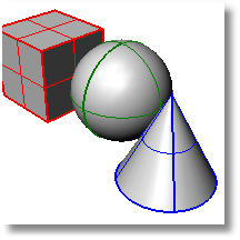
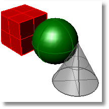
Specifies the display attributes for objects.
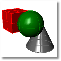
Shade-highlight selected surfaces and polysurfaces
Shades entire object with highlight color.
|
|
|
Shade-highlight selected meshes
Shades entire object with highlight color.
|
|
|
Use dotted lines
Use solid lines

Line thickness
Use object color
Use the color specified in the object's Properties.
Use fixed color
Use the specified color for all control polygons.

Polygon color
Specify the color.
Hide control points
Hide object
Hide control polygon
|
|
|
Highlight control polygon
|
|
|
Control point size
|
|
|
Locked object usage
Use Application settings
Use settings specified in Options > Appearance > Colors.
Locked color
Specify the color.
Locked object appearance
Locked objects appear solid
Locked objects appear transparent
Transparency %
Draw objects behind all others
Specifies display attributes for point objects.
Point style
Square with white center
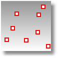
Size
Solid square
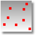
Size
PointCloud style
Square with white center
Size
Solid square
Size
PointCloud control point style
Square with white center
Size
Solid square
Size
Specifies display attributes for curves.
Curve Settings
Use object's color
Use the color specified in the object's Properties.
Use single color
Use the specified color for all curves.
Curve color
Specify the color.
Specifies display attributes for surfaces.
Surface edge settings
Use object's color
Use the color specified in the object's Properties.
Use isocurve color
Use the color specified for the isocurves.
Use single color
Use the specified color for all surface edges.
Edge color
Specify the color.
Use edge settings
Use separate settings
Edge thickness (pixels)

Color reduction %
Edge color reduction 50%.
Edge color usage
Use object's color
Use the color specified in the object's Properties.
Use isocurve color
Use the color specified for the isocurves.
Use single color
Specify the color.
Naked edge color
Specify the color.
Surface Isocurve Settings
Use object's color
Use the color specified in the object's Properties.
Use single color
Isocurve color
Specify the color.
Use specified UV colors
Use separate colors for u- and v-isocurves.
U Color/V Color
Specify the color.
Use single width
Isocurve width
Use specified UV widths
Use separate widths for u- and v-isocurves.
U width/V width
Specify the width.
Specifies display attributes for mesh objects.
Mesh Settings
Use object's color
Use the color specified in the object's Properties.
Use single color
Wireframe color
Specify the color.
Use object's color
Use the color specified in the object's Properties.
Use single color
Edge color
Specify the color.
Color reduction %
Use object's color
Use the color specified in the object's Properties.
Use single color
Naked edge color
Specify the color.
Naked edge thickness (pixels)
Color reduction %
Include in view's display menu
Include in Shade command modes
Allow assignment to individual objects
Horizontal scale
Vertical scale
Pipeline and conduits
The display pipeline handles all the drawing of viewports - wireframe, shaded, ghosted, etc. The drawing is either handled by Windows or by OpenGL graphics cards.
Windows
OpenGL
Disable all conduits
Stereo usage
Stereo mode disabled
Use hardware 3D shutter glasses
Separation
Parallax
Use anaglyph (red/blue) glasses
Custom Object Attributes Settings
Specify the color.
Specify the color.
|
|
|
Specifies the strength of the gloss color.
Specifies the range from matte to shiny.
Specifies the transparency of the object finish.
Makes the color appear to glow.
Texture
Specify a file name.
%
Transparency
Specify a file name.
%
Environment
Specify a file name.
%
|
Standard > Options Tools > Options Properties > Options (Right click) Standard > Options (Right click)
Tools > Options |
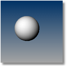
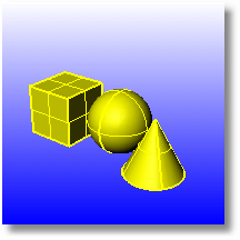
Toggles gradient view mode.
Displays a customizable color gradient as a viewport background.
Steps:
Defaults to two colors top-to-bottom.
The command acts as a "toggle." Run it once to turn gradient background on, run it again to turn it off.
|
|
|
The hyphenated version adds command line options.
Options
View
Determines the state of all viewports. Choosing the Active option turns off gradient background in all of the views except the active viewport.
All
Applies the gradient settings to all of the views.
Active
Applies the gradient settings to the active view.
State
On
Turns gradient background on.
Off
Turns gradient background off.
Top
Sets the color for the top of the gradient.
Bottom
Sets the color for the bottom of the gradient.
Colors
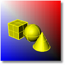
Sets the color mode to 2 or 4. If the number of colors is set to 4, more color options appear: TopLeft, TopRight, BottomLeft, and BottomRight.
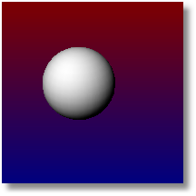
Example:
Set two-color gradient that goes from red to blue (top-to-bottom):
! -GradientView _Colors=2 _Top=128,0,0 _Bottom=0,0,128 Enter
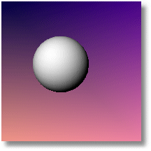
Set four-color gradient that goes from a blue-violet to a pink-salmon
! -GradientView _Colors=4 _TopLeft=0,0,64 _TopRight=70,0,140 _BottomLeft=240,150,135 _BottomRight=240,130,164 Enter
|
None
None |
Sets a specific display mode from the list of existing built-in and customized display modes.
Note: To set a mode name that has spaces, use either of the following formats:
-_SetDisplayMode Mode=MyCoolMode
-_SetDisplayMode "My Cool Mode"
Options
|
None
None |