![]()
Standard > Linear Dimension
Dimension > Linear Dimension
![]()
Dimension > Linear Dimension
Creates horizontal or vertical linear dimensions.
Steps:
Pick the first point.
Pick the second point.
Pick the dimension line location.
Note: Dimensions always measure as though the object were projected to the current construction plane.
Options
Style
Enter the dimension style name.
Draws the dimension aligned with the construction plane y-axis.
Draws the dimension aligned with the construction plane x-axis.
|
Standard > Linear Dimension Dimension > Linear Dimension
Dimension > Linear Dimension |
Creates a linear dimension lined up with two points.
Steps:
Pick the first point.
Pick the second point.
Pick the location.
Options
Style
Enter the dimension style name.
|
Dimension > Aligned Dimension
Dimension > Aligned Dimension |
Dimensions the angle between two lines.
Steps:
Select a line.
Select a second line.
Pick the dimension location.
Note: You can dimension polyline segments and linear surface and polysurface edges.
Options
Style
Enter the dimension style name.
|
Dimension > Angle Dimension
Dimension > Angle Dimension |
Dimensions the diameter of a curve.
Steps:
Pick a curve.
Pick the dimension location.
Note: Dimensions always measure as though the object were projected to the current construction plane.
Options
Style
Enter the dimension style name.
|
Dimension > Diameter Dimension
Dimension > Diameter Dimension |
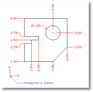
Creates dimensions from an origin point to a feature.
Ordinate dimensions show the horizontal or vertical distance from an origin point (called the basepoint) to a dimensioned feature, such as a hole center or a feature in a part. Ordinate dimensions are widely used in CNC related manufacturing industries because the clutter caused by dimensions is minimized. This type of dimension prevents accumulated errors by showing the X or Y offset of the feature from the basepoint.
Steps:
Pick a dimension point.
An XDatum dimension is implied if your second pick is primarily above or below the first pick.
A YDatum dimension is implied if your second pick is primarily left or right from the first pick.
Pick a leader endpoint.
Press Enter when finished placing dimensions.
Note: The shape of the ordinate leader can be point edited after creation to avoid overlapping geometry.
Options
Style
Enter the dimension style name.
XDatum
Overrides the implied biasing and forces an X-ordinate dimension.
YDatum
Overrides the implied biasing and forces a Y-ordinate dimension.
Basepoint
Changes the basepoint for the duration of the command. The basepoint reverts to the default construction plane origin when the DimOrdinate command is run again.
|
Dimension > Ordinate dimension
Dimension > Ordinate Dimension |
Dimension a radius of an arc or circle.
Steps:
Notes
Dimensions always measure as though the object were projected to the current construction plane.
Options
Style
Enter the dimension style name.
|
Dimension > Radial Dimension
Dimension > Radial Dimension |
Creates a linear dimension that is rotated from the x-y axis.
Steps:
Pick two points to establish a rotation angle.
Pick the first dimension point.
Pick the second dimension point.
Pick the dimension location.
Options
Style
Enter the dimension style name.
|
Dimension > Rotated Dimension
Dimension > Rotated Dimension |
Returns dimension text that has been moved back to its default location.
Steps:
Select dimensions.
Note: To move dimension text away from the dimension line, turn on the dimension control points and drag the text control point.
|
Dimension > Recenter Dimension Text
Dimension > Recenter Dimension Text |
Draws an annotation leader with arrowhead and attached text.
Steps:
Pick the head of the leader.
This is the arrow end.
Pick the next points of the leader.
Press Enter to end the command.
Note: Dimension options control the text height and arrow size.
|
Dimension > Leader
Dimension > Leader |
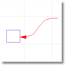
Creates or removes an annotation arrowhead on the end of a curve.
Steps:
Pick a curve near the end where you want to place an arrowhead.
Note: The arrowhead size cannot be changed.
|
Annotate > Add/Remove Arrowhead to Curve
None |