![]()
Geometry Fix > Check mesh objects for errors
![]()
None
Checks mesh objects for errors, which helps clean up, repair, and close mesh files for rapid prototype printing.
Steps:
Select mesh objects.
Use the CheckMesh command when generating an STL mesh for rapid prototyping to troubleshoot imported and Rhino-generated meshes. Using CheckMesh and then fixing any indicated errors will minimize down-process errors. The command test results along with detailed information about the mesh. Use this information as a checklist for mesh repair.
Errors
Degenerate faces
Fix with the CullDegenerateMeshFaces command.
Zero length edges
Zero-length edges typically are the result of degenerate faces. Fix with the CullDegenerateMeshFaces command.
Non manifold edges
Use the CullDegenerateMeshFaces command and then fix with the ExtractNonManifoldMeshEdges command.
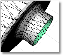
Naked edges
Naked edges are allowed, but cause problems with rapid prototyping. Use the ShowEdges command to help find them. Try the FillMeshHole, FillMeshHoles, or MatchMeshEdge commands to remove naked edges.
Duplicate faces
Fix with the ExtractDuplicateMeshFaces command.
Faces that could make it better if their directions were flipped
Fix with the UnifyMeshNormals command.
Disjoint pieces
Fix with the SplitDisjointMesh command.
Unused vertices
Unused vertices do not usually cause a problem, and there are no commands to for removing them.
Text Window Options
Copy All
Copies all text in the window to the Clipboard
Save As
Saves the contents of the window to a text file.
Close
Closes the window.
|
Geometry Fix > Check mesh objects for errors
None |
Deletes mesh faces that have 0 area, which helps clean up, repair, and close mesh files for rapid prototype printing.
Steps:
Select mesh objects.
Note: If any vertices are orphaned in the process, they are also removed
|
Mesh Tools > Cull degenerate mesh faces
Mesh > Mesh Edit Tools > Cull Degenerate Mesh Faces |
Fills a mesh hole with a single mesh face, which helps clean up, repair, and close mesh files for rapid prototype printing.
Steps:
Select two edges or vertices of a mesh.
Options
JoinMesh
If Yes, the new faces are joined to the original mesh.
|
Mesh Tools > Add a mesh face
Mesh > Mesh Repair Tools > Patch Single Face |
Fills a selected hole, which helps clean up, repair, and close mesh files for rapid prototype printing.
Fills a hole in the mesh selected by picking the hole edge. The command searches around the naked edge you select and attempts to create a closed boundary to fill.
Steps
Select a mesh hole boundary.
Note: Mesh boundaries and other subparts cannot be selected in a shaded view.
Options
JoinMesh
If Yes, the new faces are joined to the original mesh.
|
Mesh Tools > Fill Mesh Hole
Mesh > Mesh Repair Tools > Fill Hole |
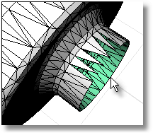
Fills all holes in a polygon mesh object with triangular faces, which helps clean up, repair, and close mesh files for rapid prototype printing.
Steps:
Select mesh objects.
|
Mesh Tools > Fill all holes in mesh (Right click)
Mesh > Mesh Repair Tools > Fill Holes |
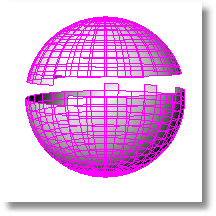
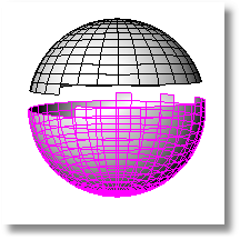
Changes the normal direction of the faces in a mesh object so they all point in a consistent direction, which helps clean up, repair, and close mesh files for rapid prototype printing.
Steps:
Select a single unjoined mesh.
The normals of all the faces of the mesh will now point to one side of the mesh.
The UnifyMeshNormals command changes the direction of the surface normals of a mesh object so all normals face the same direction. This command is useful for tidying up your mesh objects for export into 3D Studio. Rhino's Advanced Display Settings let you display the front and back faces in different colors. This will show you whether the normals need to be unified.
Notes
If UnifyMeshNormals doesn't seem to affect your mesh, explode it. Once the normals are correct, re-join the meshes.
A polygon can have two types of normals: vertex normals and a face normal.
All polygons have a face normal direction, but many polygon meshes do not have vertex normals. For example, 3DFace objects, mesh primitives, and polygon meshes imported in formats other than 3DM and 3DS do not have vertex normals.
In general, the order of the vertices in a polygon determines the face normal direction. The order of the vertices should be either clockwise or counterclockwise. You can determine the normal direction from the vertices using the right-hand rule.
You use the UnifyMeshNormals command primarily to make sure that the vertex order of all polygons in welded mesh is the same.
Example
A potential work flow is as follows:
Import STL file with holes in it.
Fill the holes in the mesh.
Weld the mesh setting the welding angle to 180 to make sure all vertices get welded.
Use UnifyMeshNormals.
Turn on one sided rendering and shade the model to see if the mesh face normals point in or out. If you see inside the mesh, normals point the wrong way.
Use Flip to change the mesh normal direction if necessary.
Export in desired format.
|
Mesh > Unify Mesh Normals STL Tools > Unify Mesh Normals
Mesh > Mesh Repair Tools > Unify Normals |
Forces mesh vertices within a specified distance to the same location, which helps clean up, repair, and close mesh files for rapid prototype printing.
Steps:
Select mesh objects or click an option.
If the distances between mesh vertices are smaller than the value of DistanceToAdjust, the vertices are forced together.
This command is useful for fixing areas that have many vertices that should be in the same spot but for some reason are not.
Options
SelectVertices
Select vertices to align.
SelectNakedEdges
Select naked edges to align all vertices on the edge.
DistanceToAdjust
Set the tolerance distance.
|
Mesh Tools > Align mesh vertices to tolerance
Mesh > Mesh Repair Tools > Align Mesh Vertices |
Strips texture coordinate, vertex colors, surface curvatures and surface parameters from a mesh and recreates only the face and vertex normals, which helps clean up, repair, and close mesh files for rapid prototype printing.
Vertices and faces are kept. Face normals and vertex normals are recalculated. Texture coordinates, vertex colors, surface curvatures, and surfaces parameters are not replaced. Use this command to rebuild meshes that are not acting properly.
Steps:
Select mesh objects.
|
Mesh Tools > Rebuild mesh
Mesh Tools > Rebuild mesh |
Removes mesh normals and reconstructs the face and vertex normals based on the orientation of the faces, which helps clean up, repair, and close mesh files for rapid prototype printing.
Steps:
Select mesh objects.
|
Mesh Tools > Rebuild mesh normals
Mesh > Mesh Repair Tools > Rebuild Mesh Normals |
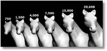
Reduces the number of polygons in a polygon mesh and converts mesh quadrangles to triangles.
Steps:
Select mesh objects.
Set the new polygon count.
To see the results of the reduction, click Preview.
Notes
If the mesh has quadrangles in it, the count of starting triangles is the number of triangles after all of the quadrangles are split. Only triangles can be made in the new mesh, so it is possible to reduce the mesh and have more faces than you started with.
It is possible to end up with meshes whose edges are shared by more than two faces (non-manifold), which may be undesirable in some cases. For one thing, this makes it hard to tell where the inside is.
|
Mesh > Reduce Mesh Polygon Count
Mesh > Mesh Edit Tools > Collapse > Reduce Vertex Count |
Removes selected mesh faces from the parent mesh creating a hole, which helps clean up, repair, and close mesh files for rapid prototype printing.
Steps:
Select mesh faces.
Note: This command is most effective in a shaded display mode since then the user can pick within a shaded mesh facet to select it.
|
Mesh Tools > Delete mesh faces
Mesh > Mesh Edit Tools > Delete Mesh Faces |
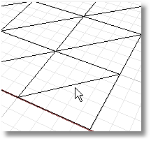
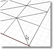
Transposes the corners of mesh triangles that share an edge, which helps clean up, repair, and close mesh files for rapid prototype printing. The edge must be shared by two faces.
Steps:
Select a shared mesh edge.
Note: Mesh edges and other subparts cannot be selected in a shaded view.
|
Mesh Tools > Swap mesh edge
Mesh > Mesh Repair Tools > Swap Edge |
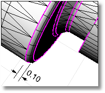
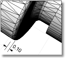
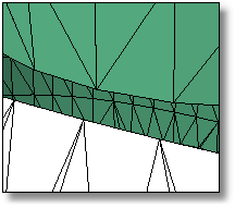
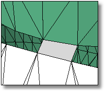
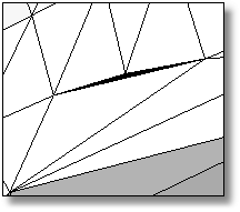
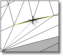
Moves face edges of an open mesh to meet adjacent face edges exactly so the mesh will be closed, which helps clean up, repair, and close mesh files for rapid prototype printing.
First, the command will try to match vertices, then it will try to split edges to make the edges match. No part of the mesh is moved more than the specified tolerance.
You can use this command either on the complete mesh or on selected edges.
When selecting a whole mesh, using a high tolerance can create unexpected results. Use larger tolerances only if you select specific edges to close.
Before edge matching, magenta edges are open. The size of the fillet is labeled.
Steps:
Select a mesh edge.
Options
PickEdges
Select specific edges to match.
DistanceToAdjust
Set the tolerance distance.
RatchetMode
If Yes, matching the mesh takes place in four passes starting at a tolerance that is smaller than your specified tolerance and working up to the specified tolerance with successive passes. This matches small edges first and works up to larger edges.
|
Mesh > Match mesh edges Mesh Tools > Match mesh edges
Mesh > Mesh Repair Tools > Match Mesh Edge |
Divides into separate mesh objects meshes that do not connect, but are still one object, which helps clean up, repair, and close mesh files for rapid prototype printing.
Steps:
Select a mesh.
A mesh object has the ability to appear to be separate objects while still belonging to the same mesh.
This can happen due to mesh editing or by importing a mesh in this condition.
|
Mesh Tools > Split disjoint mesh
Mesh > Mesh Repair Tools > Split Disjoint Mesh |
Divides a mesh edge to create two or more triangles, which helps clean up, repair, and close mesh files for rapid prototype printing.
Steps:
Use the SplitMeshEdge command to specify how you want to split faces, and then match an adjacent mesh using the MatchMeshEdge command.
|
Mesh Tools > Split a mesh edge
Mesh > Mesh Repair Tools > Split Edge |
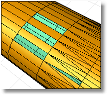
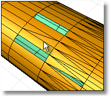
Uses a false-color display to evaluate the distances between two surfaces.
Steps:
Type the minimum or maximum acceptable thickness.
Example:
The thickness analysis dialog box has a range of values.
Blue = B; Red = R
Assume 0 < R < B.
For each analysis mesh vertex V, Rhino searches for a point P on "the other side".
d = the distance from P to V.
If d <= R, the vertex V is red.
If d > B, the vertex is white.
If R <= d <= B, the vertex is the appropriate color in the range from red to blue.
The percentage reported is the percentage of analysis mesh vertices that are not white. In this example, it is the percentage of the analysis mesh vertices whose distance to the "other side" point is <= B.
|
Surface Analysis > Thickness Analysis
None |
Turns the false color thickness analysis display off.
|
Surface Analysis > Thickness Analysis Off (Right click)
None |